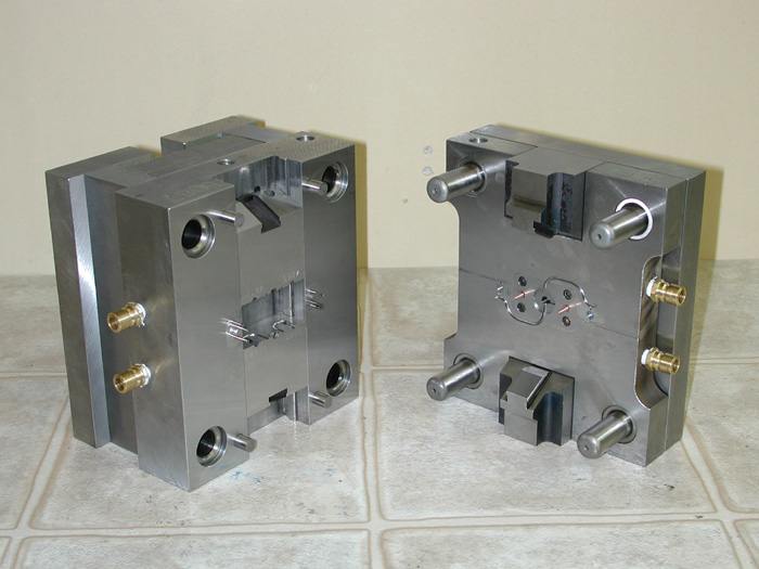
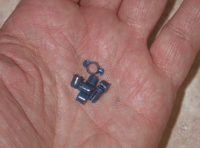
Here is a mold-build in more detail. The parts are for a dental application and are fairly small; a few grams apiece. The mold is 5″ x 6″ and about 7″ tall. This is a “simple” mold because it is essentially two flat blocks of steel with the proper shapes cut into them into which molten plastic is squirted. There is no complicated mechanical action in this tool other than the ejector system that allows the cooled parts to be pushed free. This is the least expensive style of mold; it is smaller and much simpler than the two-slide mold shown below even though the parts are larger and there are two more cavities in this mold.
This is a fully hardened, high volume production tool. All the cavities were made with sinker and wire EDM so everything was burned after hardening and grinding. The small size of this mold meant that the main mold plates could be made from solid blocks of tool steel…it’s far more common to machine rectangular pockets in the mold set and bolt in smaller tool steel cavity inserts. It’s a lot less work to do it in the solid, but the tool steel gets very expensive in larger blocks.
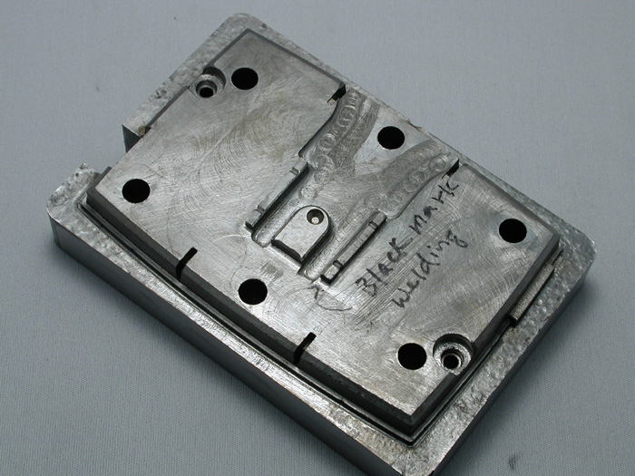
After the mold was almost finished, the inventor decided on a new color scheme for his parts that required each to be molded separately, and also added a new part to his design that needed to be accommodated in this tool. A valve had to be added to allow a single pair of parts to be molded without filling the other cavities, and two new cavities had to be squeezed in too. This decision added cost…almost a third of the final build price, mostly because the blocks were already hardened and ground by the time of the new decision, and the four original cavities had been burned in and couldn’t be moved without welding and re-burning. All of the preliminary work (like drilling and tapping holes) that could have been done in minutes in the soft steel blocks took hours in the hardened ones. Additional parts also had to be made, and some of the original work had to be scrapped.

This is how a mold starts; a bunch of rough sawcut blocks on the bench. The two upper blocks are the main mold plates which will be hardened. Everything else is 4140 prehard.

I make sinker electrodes from a copper alloy called Telco; I find the graphite usually used for EDM electrodes to be extremely messy to machine. Telco is easy to cut, and makes for easy housekeeping too. The blocks are sawcut from a slab like this one, and are milled and ground to accurate dimensions and mounted into an electrode holder. They are then machined to final shape by milling, turning, wire EDM, and grinding.

All of the mold blocks have been machined, the cooling lines have been drilled, the ejector pin holes drilled and reamed, the pin retaining plate in the foreground has been counterbored for the ejector pin heads, and the bolt and dowel pin holes drilled tapped and reamed. The locating ring seat and knockout holes have also been cut. Sitting on the ejector plate are two prototype parts that will be duplicated in this mold. Notice the absence of mold cavities in the main plates; these will be machined after hardening by EDM machining.

The mold plates looking rather rough after hardening..they will now be surface ground to size and fitted accurately together. In addition, the leader pin bores will be cut together on the wire EDM so they align perfectly, allowing the mold halves to register precisely together. Additionally, the sprue bore that admits the plastic to the mold will be wire EDM cut to a 1/2 degree taper and a very smooth finish…the hemispherical recess that the extruder nozzle presses against has already been machined before hardening.

Here is the first of many electrodes; 22 in total to rough and finish burn all the cavities. Some cavities required as many as three roughing and three finishing electrodes. The holder is a precision vise that can be mounted very repeatably to either the milling machine table or to the EDM ram allowing me to preserve the origin position so I can just load the part into the machine and run the program to either cut it or burn with it.

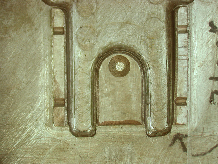
The first cavity rough burned into the cold side mold plate. A second electrode will be used to clean up the sharp corners which tend to be eroded first from the electrodes. Notice the rough texture…this part needs to be rough, and sinker EDM is the perfect way to create the required texture.

On the left and right sides are a pair of cavities that needed 3 different electrodes. This was done to make the electrodes simpler to fabricate. The electrode blank was made big enough for all three trodes, the first was cut and used, then it was milled away, and the next electrode was cut on the same block using the same origin so the individual burns would align properly.
Here is the first electrode after it’s been used. Actually, this shape was cut 4 times. it made one roughing burn, then it was re-cut and made the first finishing burn. It was then re-used for the next roughing burn, then re-cut again etc etc until all 4 cavities were burned.

Here is the trode for the second burn.

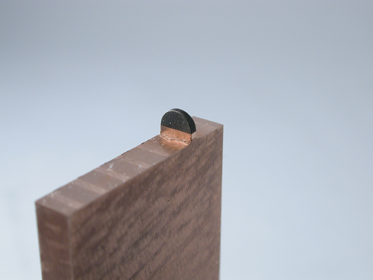
And here is the last trode of the three. As before, each electrode was used for a pair of burns; a finishing burn on a previously roughed cavity while it was unworn, and then again to rough out the next cavity detail. Then it was milled away, and a new electrode cut on the copper blank. By the way, this copper blank measures 0.950″ wide and 0.165″ thick.

This was the original plan for the mold…all cavities were to be filled in a single shot. The yellow part is the runner system that feeds plastic into the cavities, modeled in Solidworks. This plan had to be abandoned when the inventor decided to mold the parts in different colours. This meant putting a directional valve into the runner system so a pair of cavities could be filled independently of the other pair. The inventor also had an inspiration late in the design cycle that resulted in a whole new part. This was the only mold that could accommodate the new part, so we decided to crowd it in.

This is the new cavity layout seen from above. It’s a lot more crowded than I’d normally design, but it works just fine. The two new cavities are an awkward shape. They are very thin; only 0.030″ and parallel sided with no draft at all. This means normal ejector pins cannot be used to push these parts from the cavities. A decision was made to use custom profiled ejector blades wire EDM cut from A2 tool steel. This allowed me to also wire EDM the cavities right through the cold side mold plate, so I could capitalize on the very fine finish a wire EDM is capable of.

The first task is to get a start hole through the hardened mold plate. Normally a specialized EDM called a “Hole Popper” is used for this…I chose to do it on the sinker EDM with a Rotobore attachment and a hollow copper electrode. Once this step was complete, the plate was mounted to the wire EDM and the cavities wirecut to shape.

While the start holes were burning on the sinker, the wire EDM was used to cut the ejector blades and the blade heads. The finished blades were used as gauges to size the cavities, ensuring that the proper clearance for venting was maintained (0.0003″ per side). Once I could just force a blade into the cavity, I programmed a final skim cut for my clearance and called it good. The heads were pinned to the blades using tapered pins; one of them is quite prominently visible in the photo.

The vent pins used to eliminate air entrapment on a tiny feature in the hotside were also cut on the wire EDM using the rotary axis. They have features that are hard to make any other way. They have 24 flats around the periphery and the skinny end is nominally 0.0393″ diameter (1.0 mm). The flats create 0.0002″ air gaps between the pin and the wall of its mating hole…enough to let the air out but not let the molten plastic out. There are also big flats and crisscross grooves cut into the pin body and head for the same purpose.

The work on the sprue had to be scrapped to enable a valve to be made. A sprue bushing was installed and made rotatable so the molder could select the orientation. A capscrew locks the bushing in place. Here’s how to tap a hole if your block is already hardened. A start hole is drilled with a carbide drill, then a custom electrode is dropped into the hole and orbited out to diameter on the sinker EDM. The hemispherical recess in the background will be wire EDM cut away in the next operation to make room for the sprue bushing.

The sprue bushing was made with a 5 degree tapered body to enable it to mate and seal against the cold side of the mold. (There is a step in the parting line that forced me to make this elaborate feature). Here, the recess in the cold side is sinker EDM cut to fit the tip of the sprue bushing perfectly. The sinker is capable of very accurate material removal; I can orbit out in 0.0001″ increments until the fit is perfect. The electrode is also made to rotate while burning so the recess is burned perfectly conical.

Here is the finished hotside. You can see the tip of the sprue bushing oriented to fill the two biggest cavities. Also visible is the step in the parting line that made fitting this valve so elaborate. The sprue bushing is custom made because I needed a smaller sprue taper than is commercially available.

And the finished coldside. I’ve pushed the ejector system forward so you can see how it works. A detail not readily apparent, is the way the parts are held onto the coldside so the pins can push them free. There are little undercuts strategically placed in the coldside cavities to accomplish this, and the hotside cavities are polished to make the parts release from them easily. A sticking part on the hotside is a disaster waiting to happen, often resulting in a squashed part and a wrecked mold. If you look closely you can also see the venting system machined into the parting line. This allows air to be purged from the mold as the plastic is introduced.

The finished mold on the bench and ready for testing.


Recent Comments